Anderson® PowerPole® connectors (pair: red, black)
")
")

- Item Number: aeap01-15
- Info on the variant:
- 15A, 30A or 75A Anderson® PowerPole® connector
- 1 pair red-black
- Free shipping in GER from 100 €
- Free shipping in EU from 500 €
- 45 day returns policy
- Free return shipping
15A, 30A, 45A or 75A Anderson® PowerPole® connector - 1 pair includes one connector in red + black each. The Anderson® PowerPole® connectors housings are identical, but have different contacts to fit different cable diameters (AWG = American Wire Gauge).
For electric contacts we recommend Anderson® PowerPole® connectors because of their decisive advantages:
- stackable in any order and number
- reverse current protected
- colour coded
- can either be soldered or crimped with special crimping tool
Please Note: Anderson® PowerPole® connectors do not have any male or female connector parts.
All connector housings are identical. When stacked one dovetail points upwards, the other points downwards.

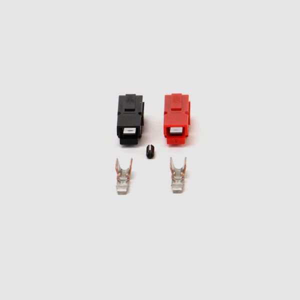
Anderson® PowerPole® connectors scope of supply:
- 1x connector housings in red
- 1x connector housings in black
- 1x fixing pin
- 2x metal contacts (here: size 15), to be selected according to cable diameter
Tools needed:
 1x crimping tool for Anderson® PowerPole® connectorss
with 15A, 30A and 45A (see shop: aeapcrimp01)
How to install Anderson® PowerPole® connectors
 pic. 1: Anderson® PowerPole® connectors are genderless connectors. They can be connected in many different ways. Mostly the stacked variety is used, as shown here.
 pic. 2: First, remove the isolation from the wire. If necessary, twist wires by hand, so they don\'t fray.
 pic. 3: Wire is inserted into the contact as shown here. Make sure that the contact is flush with the isolation and no wires remain visible.
 pic. 4: Put the contact into the slot of appropriate size (15A, 30A or 45A). Make sure the contact hook points downwards. After crimping, check that the contact fits the wires tightly by pulling them.
The most common problem source is a badly crimped contact. Check in advance if the contact has been crimped correctly by pulling the cable. The cable must not disconnect from the contact.
Three examples for incorrect crimping:

Example 1:
Wires must not protrude from the contacts.

Example 2:
There must be no gap between contact and isolation. Contact must be flush with the wires.

Example 3:
The contact\'s hook must not point upwards.
 pic. 5: Inside the connector housings there\'s small metal latches. Insert contact into housing. The hooks must point downwards in order to lock behind the metal latch. When you hear a click, the contact has reached its correct position.
 pic. 6: If the contact is properly inserted you can see the hook when you look at the connector from the front. Pull the cable to make sure it is fixed tightly with the housing.
 pic. 7: Connect housing by sliding one into the other. In the end the red housing has to be on the right side. Finally insert the fixing pin into the round opening.
 pic. 8: Finally, stack the Anderson® PowerPole® connectors as shown.
How to remove contacts from the Anderson® PowerPole® connectors
 pic. 9: To remove the contact from the housing lift the contact hook with a small screwdriver. This way the fixture loosens and you can remove the cable.
 pic. 10: After the removal of the contact the hook may be bent. Before inserting it again, you should bend it back to its correct form.
 pic. 11: This is how the contact should eventually look like. The hook is in upright position again and can be continued to use.
Anderson® PowerPole® Stecker Lieferumfang:
- 1x Steckergehäuse in rot (a)
- 1x Steckergehäuse in schwarz (a)
- 1x Fixierstift (b)
- 2x Kontakte (c)
Benötigtes Werkzeug:
1x Crimpzange für Anderson® PowerPole® Stecker
mit 15A, 30A und 45A (im Shop: aeapcrimp01)
So montieren Sie die Anderson® PowerPole® Stecker
Abb. 1: Die Anderson® PowerPole® Stecker sind geschlechtslose Stecker. Sie lassen sich auf verschiedene Weisen kombinieren. Meistens wird eine aneinandergereihte Position, wie hier abgebildet, verwendet. Das rote Gehäuse steht für den Pluspol, das schwarze Gehäuse für den Minuspol. Abb. 2: Entfernen Sie zunächst die Isolierung der Drähte. Falls nötig, drehen Sie die Drähte mit der Hand in Form, damit sie nicht ausfransen. Abb. 3: Der Draht wird wie abgebildet in den Kontakt eingeführt. Achten Sie darauf, dass der Kontakt bündig mit der Isolierung abschließt und keine Drähte mehr zu sehen sind. Abb. 4: Legen Sie den Kontakt in die Aussparung der passenden Größe (15A, 30A oder 45A). Achten Sie darauf, dass der Haken des Kontaktes dabei nach unten gerichtet ist. Testen Sie nach dem Crimpen, ob der Kontakt fest auf den Drähten sitzt, indem Sie daran ziehen.
Eine häufige Problemquelle ist ein falsch gecrimpter Kontakt. Kontrollieren Sie deshalb bereits vorab, ob der Kontakt richtig gecrimpt wurde, indem Sie an dem Kabel ziehen. Hierbei darf sich das Kabel nicht aus dem Kontakt lösen.
Drei Beispiele für falsches Crimpen:
Beispiel 1:
Es dürfen keine Drähte aus den Kontakten herausragen.
Beispiel 2:
Zwischen Kontakt und Isolierung darf keine Lücke entstehen. Der Kontakt muss bündig abschließen.
Beispiel 3:
Der Haken des Kontaktes darf nicht nach oben zeigen.
Abb. 5: In den Steckergehäusen befinden sich kleine Metallzungen. Führen Sie die Kontakte in das Gehäuse ein. Die Haken müssen dabei wieder nach unten zeigen, damit sie sich hinter die Metallzunge klemmen können. Wenn Sie ein Klicken hören, dann hat der Kontakt die richtige Position erreicht. Abb. 6: Wenn Sie die Kontakte richtig eingesteckt haben, können Sie den Haken sehen, wenn Sie frontal auf den Stecker schauen. Ziehen Sie an dem Kabel, um sicher zu gehen, dass es fest im Gehäuse steckt.
Abb. 7: Schieben Sie die Steckergehäuse ineinander. Das rote Gehäuse sollte sich am Ende auf der rechten Seite befinden. Stecken Sie zum Schluss den Fixierstift in die runde Öffnung.
Abb. 8: Fügen Sie zum Schluss die Anderson® PowerPole® Stecker wie abgebildet aneinander.
So lösen Sie die Kontakte aus den Anderson® PowerPole® Steckern
Abb. 9: Um den Kontakt aus dem Gehäuse zu entfernen, heben Sie mit einem kleinen Schraubenzieher den Haken des Kontaktes an. Dadurch lockert sich die Halterung und Sie können das Kabel rausziehen.
Abb. 10: Nach dem Entfernen des Kontaktes kann es passieren, dass der Haken verbogen ist. Vor dem erneuten Einstecken sollten Sie ihn wieder in Form biegen. Abb. 11: So sollte der Kontakt schlussendlich aussehen. Der Haken ist wieder in senkrechter Position und kann nun weiter verwendet werden.


 - 30A")


")


")


")
 mit Schutzkappe rot zum Löten")
 mit Schutzkappe rot zum Löten")
 mit Schutzkappe schwarz zum Löten")
 mit Schutzkappe schwarz zum Löten")
")
 & L1019 (w)")
")


