Set di connettori JST per automontaggio
Prezzi incl. IVA più spese di spedizione
Pronto per la spedizione di oggi,
tempo di consegna ca. 1-3 giorni lavorativi
- Numero Ordine: aejsts01
- Livraison gratuite dans l'UE à partir de €500
- 45 jours droit de retour
- Retours gratuits et faciles
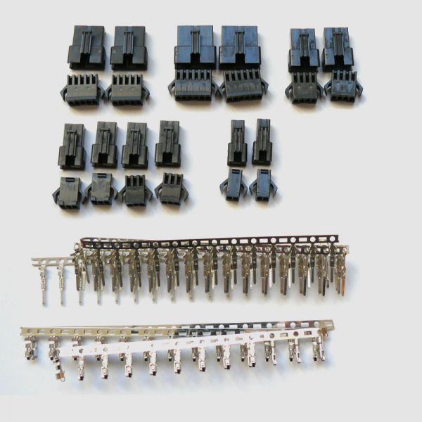
Using this connector set you can easily adjust your e-bike components to a single standard.
Included two of each (socket and plug housings):
- 2x 2-pin e.g. for brake levers
- 4x 3-pin e.g. for PAS sensors or power throttles
- 3x 4-pin e.g. for power throttles with voltage display
- 2x 5-pin e.g. for hall sensor cables
- 2x 6-pin perfect for CycleAnalysts (directly compatible)
- The appropriate amount of contacts for plug-in
Cables can either be soldered or crimped.
Tools needed:
 1x crimping tool for JST connectors (see shop: aejstcrimp02)
 How to install JST connectors
(shown here with 4-pin connector) pic. 1: First, remove the isolation from the wire. Make sure the uncovered wires are not longer than 3mm. If too much isolation has been removed the contact can no longer be inserted into the housing.
  pic. 2: Crimp the wire as shown in the picture. Make sure the isolation reaches up to the central notch. Check if the wire is of correct length and does not protrude the crimped area.
  pic. 3: Repeat this process for the female contact.
 The most common source for problems is a badly crimped contact. Check in advance if the contact is crimped correctly by pulling the cable. The cable must not disconnect from the contact.
Two examples for incorrect crimping:

Example 1:
Isolation must not be outside of crimped area.
Example 2:
Wire must not protrude forward from the crimped area. pic. 4: Position the contact inside the crimping tool as shown.
  pic. 5: Contact should be positioned along the two different levels of the crimping tool, as shown here. The higher level crimps more forcefully and is used for wires while the lower level provides lower force and fixes the isolation.
  pic. 6: Example of a completely crimped male contact.
  pic. 7: Example of a completely crimped female contact.
  pic. 8: Insert the male contact into the connector housing. The hook must be inserted into the constriction. Repeat this process for the remaining three cables.
  pic. 9: The female contact is inserted into the constriction in the same spot as the male contact. Repeat this process for the remaining three cables.
  pic. 10: After connecting the female contact is visible inside the housing. You can check for proper connection by slightly pulling the cable.
  pic. 11: After connecting the male contact protrudes from the housing. You can check for proper connection by slightly pulling the cable.
  pic. 12: Connect the housings as shown.
 How to remove contacts from the JST-sockets
 pic. 13: Shove a narrow screwdriver through the socket This way the hooked contact will be bent downwards and you can remove the contact.
  pic. 14: You disconnect the male contact by sticking e.g. a paper clip through the small gap above the tab and pushing it against the hook.
  pic. 15: Do not forget to bend the hook back to an upright position, afterwards. Now you can continue using the contact.
 Benötigtes Werkzeug:
1x Crimpzange für JST-Steckverbindungen (im Shop: aejstcrimp03)
So montieren Sie die JST-Stecker
(am Beispiel des 4-pin Steckers)
Abb. 1: Entfernen Sie zunächst die Isolierung der Drähte. Achten Sie darauf, dass die freigelegten Drähte höchsten 3mm lang sind. Wenn zu viel Isolierung entfernt wurde, kann der Kontakt nicht mehr in das Gehäuse eingesteckt werden. Abb. 2: Crimpen (verquetschen) Sie den Draht, wie in der Abbildung gezeigt, zusammen. Achten Sie darauf, dass die Isolierung bis zur mittigen Einbuchtung reicht. Kontrollieren Sie, ob der Draht die richtige Länge hat und nicht über die Crimpfläche hinaus ragt. Abb. 3: Wiederholen Sie den Vorgang auch für den weiblichen Kontakt.
Eine häufige Problemquelle ist ein falsch gecrimpter Kontakt. Kontrollieren Sie deshalb bereits vorab, ob der Kontakt richtig gecrimpt wurde, indem Sie an dem Kabel ziehen. Hierbei darf sich das Kabel nicht aus dem Kontakt lösen.
Zwei Beispiele für falsches Crimpen:
Beispiel 1:
Die Isolierung darf sich nicht außerhalb der Crimpfläche befinden.
Beispiel 2:
Der Draht darf nicht zu weit aus der Crimpfläche nach vorne herausragen.
Abb. 4: Positionieren Sie den Kontakt wie gezeigt in der Crimpzange. Abb. 5: Der Kontakt sollte an die zwei verschiedenen Ebenen der Crimpzange wie hier dargestellt angelegt werden. Die höhere Ebene crimpt stärker und wird für die Drähte verwendet, die niedrigere Ebene hingegen crimpt schwächer und fixiert die Isolierung. Abb. 6: Ein Beispiel für einen fertig gecrimpten männlichen Kontakt. Abb. 7: Ein Beispiel für einen fertig gecrimpten weiblichen Kontakt. Abb. 8: Schieben Sie den männlichen Kontakt in das Steckergehäuse. Der Haken muss dabei in die Verengung eingeführt werden. Wiederholen Sie diesen Vorgang auch für die restlichen 3 Kabel. Abb. 9: Der weibliche Kontakt wird in derselben Position wie der männliche Stecker in die Verengung eingeführt. Wiederholen Sie diesen Vorgang auch für die restlichen 3 Kabel.
Abb. 10: Der weibliche Kontakt ist nach dem Zusammenstecken im Gehäuse sichtbar. Durch leichtes Ziehen am Kabel können Sie überprüfen, ob der Kontakt richtig eingesteckt ist.
Abb. 11: Der männliche Kontakt ragt nach dem Zusammenstecken aus dem Gehäuse heraus. Durch leichtes Ziehen am Kabel können Sie überprüfen, ob der Kontakt richtig eingesteckt ist.
Abb. 12: Verbinden Sie die Steckergehäuse wie dargestellt miteinander.
So lösen Sie die Kontakte aus den JST-Steckergehäusen
Abb. 13: Drücken Sie mit einem dünnen Schraubenzieher durch das Steckergehäuse. Dadurch wird der Haken des Kontaktes nach unten gebogen und Sie können den Kontakt hinaus ziehen.
Abb. 14: Bei dem männlichen Kontakt lösen Sie die Verbindung, in dem Sie zum Beispiel mit einer Büroklammer durch die kleine Aussparung oberhalb der Nase gegen den Haken drücken. Abb. 15: Vergessen Sie nicht, den Haken danach wieder in die aufrechte Position zu biegen. Nun können Sie den Kontakt weiter verwenden.


 - 30A")


 für Controllerseite")


 u. Bedienteil-Display (bestimmte Displays)")


 Ladegeräte mit Hohlsteckern")
 Ladegeräte mit Anderson® PowerPole® Steckern")
 mit Schutzkappe schwarz zum Löten")


")
 & (w)")