Super Seal accu stekker


- Productnr. aebcwp01-p
- Informatie over de variant:
- Plug & Drive plug to connect controller and battery
- splash proof with locking device
- 2-pin, reverse polarity proof
- Gratis verzending in DE vanaf 100 €
- Gratis verzending in EU vanaf € 500
- 45 dagen recht op retour
- Gratis retourzending
EBS Battery Connectors are perfect to connect batteries to controllers. They set a new standard in terms of safety and comfort: They are splash proof, reverse polarity proof and use a locking tab that prevents accidental separation. This is why we use EBS Connectors for our Plug & Drive Conversion Kit's power supply. Suited connectors are factory issue with all batteries from Ebike Solution. Otherwise you need a male connector for your battery. Basically, EBS Battery Connectors can be used for any 2-pin connection.
Battery connectors are suited for systems with 36V and 15A continuous current.

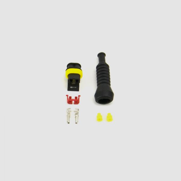
Battery connectors splash proof - female - content:
- 1x socket housing 2-pin
- 1x rubber cap 2-pin
- 2x socket contact 0,75-1,5 mm2
- 2x single conductor seal, rubber
- 1x red fixing clamp plastic

Battery connectors splash proof - male - content:
- 1x pin housing 2-pin
- 1x rubber cap 2-pin
- 2x socket contact 0,75-1,5 mm2
- 2x single conductor seal, rubber
How to assemble your custom EBS battery connector
 pic. 1: Pull cable (a) through the rubber cap (g).
 pic. 2: Remove isolation at the tips and pull cable (a) through single conductor seal (c).
 pic. 3: Crimp cable (a) to contact (b). Make sure that the yellow single conductor seal (c) is tightly crimped to the outer collar of the contact to guarantee that the connection is splash proof. Cable strand is tightly crimped to to the inner collar. Check in advance if the contact is crimped correctly by pulling the cable. The cable must not disconnect from the contact. Repeat with second cable.
 pic. 4a (for male connectors): Pin housing: Push contacts (b) into the pin housing (d). Check if the contact's small metal latches are fixed inside the housing, by carefully pulling the cable. The contact must not disconnect from the housing. Make sure that the black contact is plugged into port 1 and the red contact into port 2.
 pic. 4b (for female connectors): Socket housing: Push contacts (b) into socket housing (e). Make sure both contacts are exactly level with each other. Push red fixing clamp (f) onto the housing. Check correct fixation of clamp by carefully pulling it. Check if the contact's small metal latches are fixed inside the housing, by carefully pulling the cable. The contact must not disconnect from the housing. Make sure that the black contact is plugged into port 1 and the red contact into port 2.
 pic. 5: Pull rubber cap (g) over pin housing and socket housing.
Attention: Wrong polarity can cause short circuit. Please make sure to check for correct polarity before use.
So konfektionieren Sie Ihren EBS Akkustecker:
Abb. 1: Ziehen Sie das Kabel (a) durch die Schutzkappe (g). Abb. 2: Entfernen Sie an den Spitzen die Ummantelung der Kabel und führen Sie die Kabel (a) durch die Einzeladerabdichtung (c). Abb. 3: Crimpen (verquetschen) Sie Kabel (a) und Kontakt (b) miteinander. Achten Sie darauf, dass die gelbe Einzeladerabdichtung (c) mit der äußeren Manschette des Kontaktes fest vercrimpt ist, um den Spritzwasserschutz zu gewährleisten. Die Kabellitze wird fest mit der inneren Manschette vercrimpt. Kontrollieren Sie bereits vorab, ob der Kontakt richtig gecrimpt wurde, indem Sie an dem Kabel ziehen. Hierbei darf sich das Kabel nicht aus dem Kontakt lösen. Für das zweite Kabel wiederholen. Abb. 4a (für männlichen Stecker): Stiftgehäuse: Schieben Sie die Kontakte (b) in das Stiftgehäuse (d). Prüfen Sie, ob die kleinen Metallnasen des Kontaktes im Gehäuse eingerastet sind, indem Sie vorsichtig am Kabel ziehen. Der Kontakt darf sich nicht aus dem Gehäuse lösen. Achten Sie darauf, dass der schwarze Kontakt in Eingang 1 und der rote Kontakt in Eingang 2 eingesteckt ist.
Abb. 4b (für weiblichen Stecker): Buchsengehäuse: Schieben Sie die Kontakte (b) in das Buchsengehäuse (e). Achten Sie darauf, dass sich beide Kontakte auf gleicher Höhe befinden. Schieben Sie nun die rote Fixierklammer (f) auf das Gehäuse. Prüfen Sie den korrekten Sitz der Fixierklammer durch vorsichtiges Ziehen. Prüfen Sie, ob die kleinen Metallnasen des Kontaktes im Gehäuse eingerastet sind, indem Sie vorsichtig am Kabel ziehen. Der Kontakt darf sich nicht aus dem Gehäuse lösen. Achten Sie darauf, dass der schwarze Kontakt in Eingang 1 und der rote Kontakt in Eingang 2 eingesteckt ist.
Abb. 5: Ziehen Sie die Schutzkappe (g) über das Stift- bzw. Buchsengehäuse.
Achtung: Falsche Polarität kann einen Kurzschluss verursachen. Prüfen Sie daher vor Inbetriebnahme unbedingt, ob die Polarität korrekt ist.


 - 30A")


")


 laders met Anderson® PowerPole® aansluitingen")


")

 für Controllerseite")


 laders met barrel stekkers")

")
 met beschermkap rood om te solderen")

")


- 3450 mAh celbasis")
- 3450 mAh celbasis")


